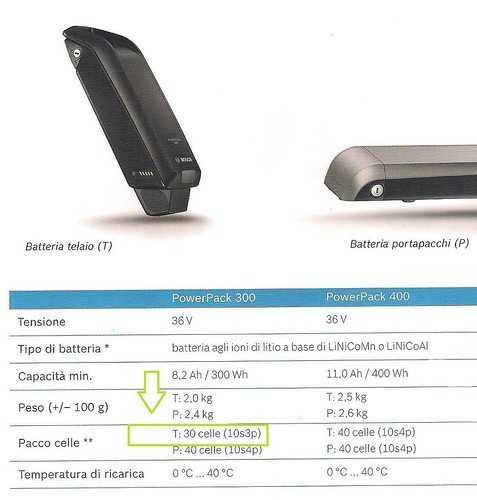
Scusa ma dove hai letto che la batteria da 300 è fatta con 30 celle? A me risulta che le celle son sempre 40, cambia non la qualità della singola cella, che è sempre ottima, ma la capacità, 2200, 2900, 3500 mAh, che è aumentata man mano che la tecnologia delle celle al litio é migliorata.
GRAZIE PER LA PRECISAZIONE......E' GIUSTO DIVULGARE NOTIZIE CERTE....TANT'E' CHE HO MODIFICATO LEGGERMENTE IL MESSAGGIO INIZIALE......
CHIEDO SCUSA...... DEVO AVER FATTO CONFUSIONE LEGGENDO L'ARTICOLO SOTTOSTANTE DOVE SI DICEVA CHE UNA BATTERIA PER AVER LE CARATTERISTICHE DI 36v E CIRCA 8.5Ah COME NEL CASO DELLA POWER PACK 300 (36v 8.2Ah ) USAVA UNA CONFIGURAZIONE 10s3p COME SEGUE:
To reach our intended voltage of 36V, we have to connect a number of 18650 cells in series. Lithium-ion battery cells are nominally rated at 3.6 or 3.7V, meaning to reach 36V nominal, we’ll need 10 cells in series. The industry abbreviation for series is ‘s’, so this pack will be known as a “10S pack” or 10 cells in series for a final pack voltage of 36V.
Next, we’ll need to wire multiple 18650 cells in parallel to reach our desired pack capacity. Each of the cells I’m using are rated at 2,900 mAh. I plan to put 3 cells in parallel, for a combined capacity of 2.9Ah x 3 cells = 8.7 Ah. The industry abbreviation for parallel cells is ‘p’, meaning that my final pack configuration is considered a “10S3P pack” with a final specification of 36V 8.7AH.
Most commercially available 36V packs are around 10Ah, meaning our pack will be just a bit smaller. We could have also gone with a 4p configuration giving us 11.6 Ah, which would have been a slightly bigger and more expensive pack. The final capacity is totally defined by your own needs. Bigger isn’t always better, especially if you’re fitting a battery into tight spaces.
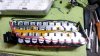
Next, plan out your cell configuration on your computer or even with a pencil and paper. This will help ensure you are laying out your pack correctly and show you the final dimensions of the pack. In my top-down drawing below I’ve designated the positive end of the cells in red and the negative end of the cells in white.
This is a very simple layout where each column of 3 cells is connected in parallel and then the 10 columns are connected across in series from left to right. The BMS board is shown at the far right end of the pack. You’ll see how the pack represented in the drawing will come together in real life shortly.